Introduction
This is a open-ended project inspired by two YouTube videos:
In this video, about V10 engines, the Hagerty guy recreates the engine sound of a straight-line 5 cylinder Audi engine by playing computer simulated cylinder explosion blips into the intakes of an exhaust manifold.
In this video Marty from MightyCarMods get a custom turbo intake modelled and 3d printed for a Daihatsu Mira. I liked the idea of modelling up a manifold in Fusion 360…but I don’t really have the enhanced car to put it in.
I figured, lets have a go:
- Model up an exhaust manifold and 3d print
- Attach some speakers to each intake
- Use some code to mimic the gas pulse in each cylinder’s explosion gas pulse
- See what noise it makes.
- (Learn some fusion 360 modelling, acoustics and whatever else enroute)
Part 1: What sound do we want?
I think its ubiquitously agreed that the V10 is one of the best sounding ICE there is (and there will ever?) be.
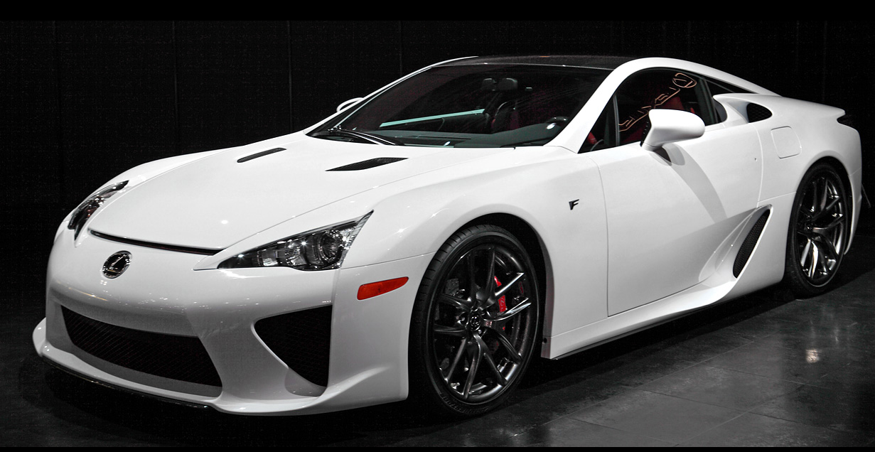
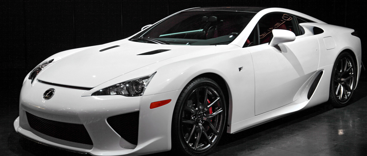
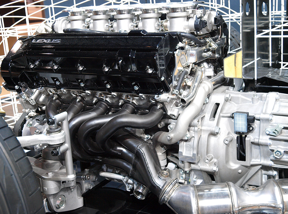
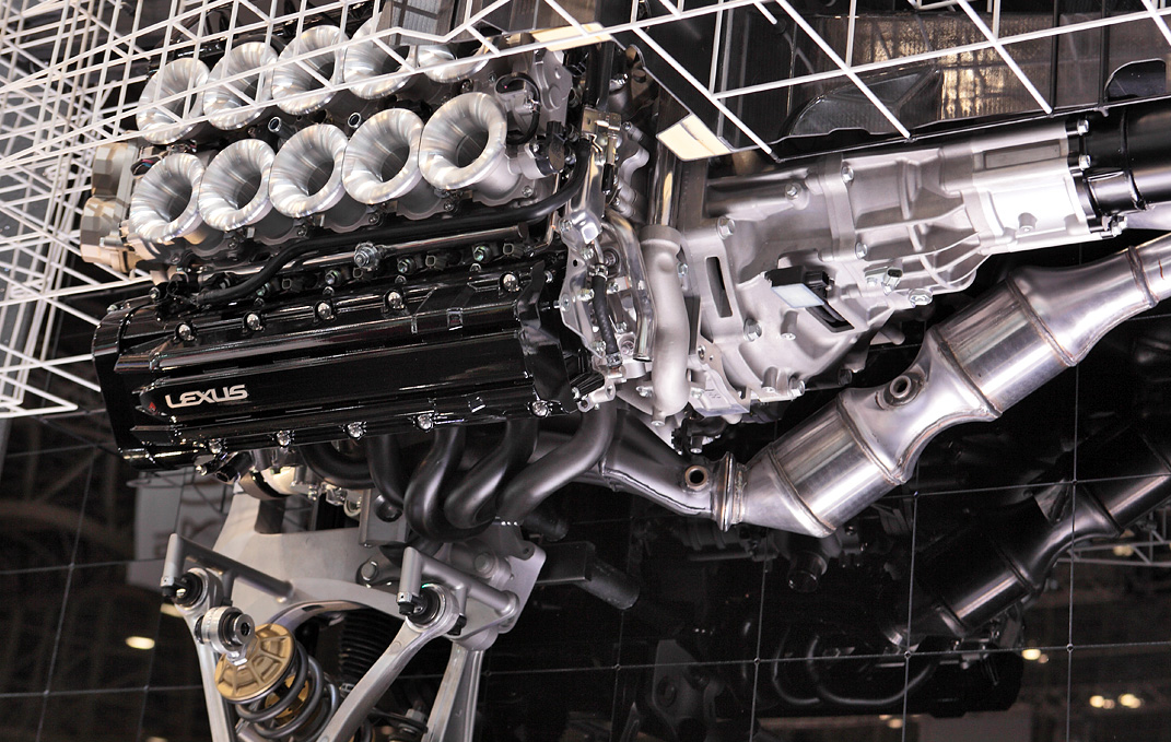
And of the V10s, the Toyota Lexus LFA is said to have one the best engine sounds of all, perhaps trumped only by F1 V10s.
As touched on in Hagerty video above the internal combustion engines principally there to turn the car wheels, but a side show is that the ICU process generates air flow and through a network of pipes, manifolds and exhausts this air flow can be tuned similar to wind and brass instruments.
Modelling in Fusion 360
There are a quite a few ‘exhaust manifold modelling’ YouTube tutorials. I looked at a few but found my Fusion 350 skills to be sufficient to wing it. The following seemed alright as a starter for 10:
These videos model an inline 4 cylinder manifold, with no particular attention to tube lengths (or anything else) though.
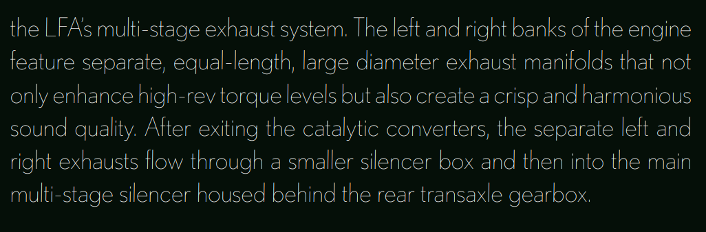
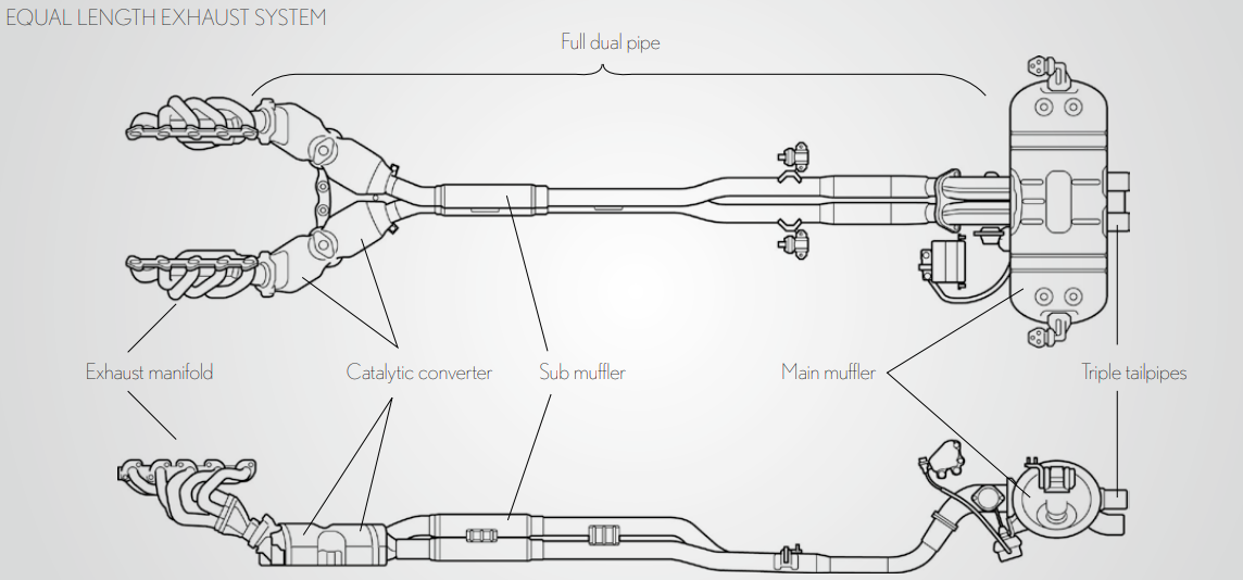
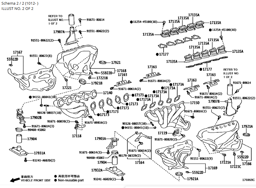
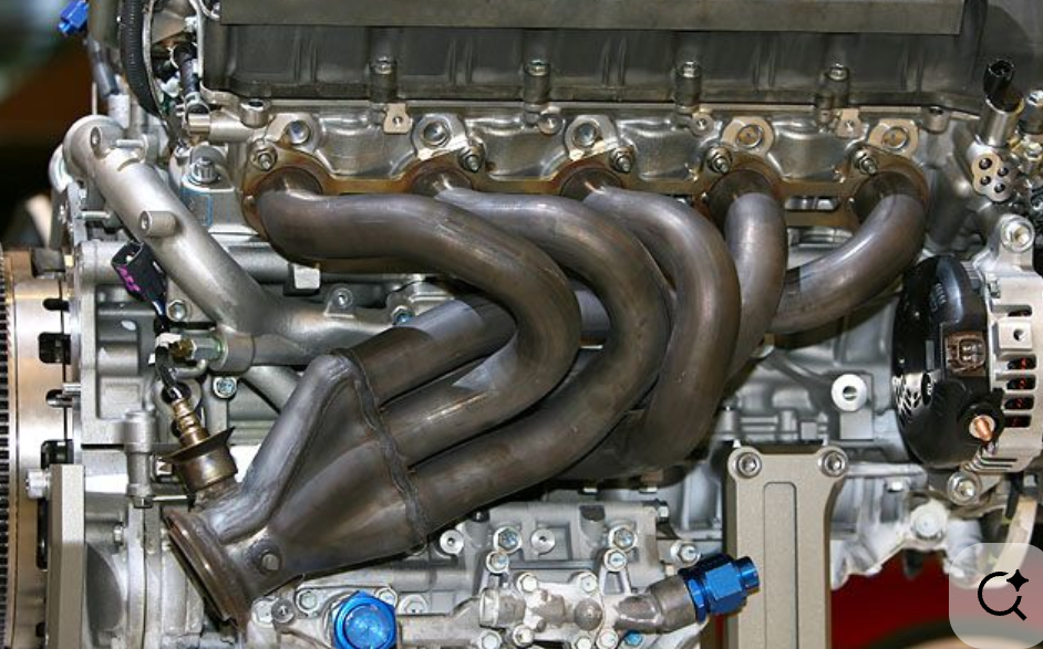
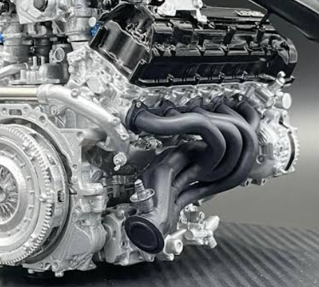
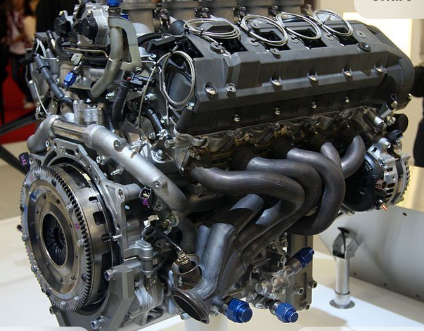
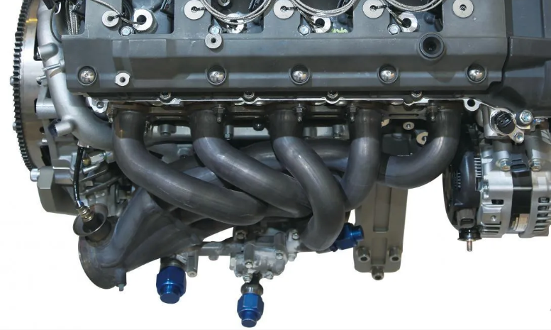
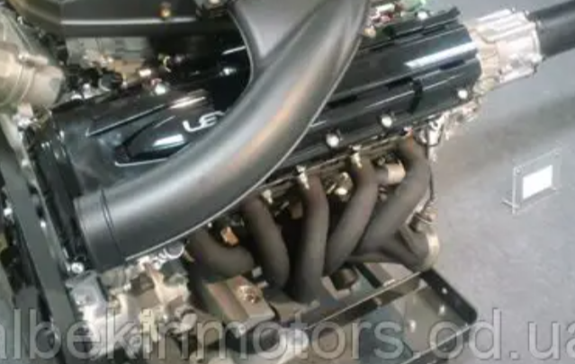
The LFA manifolds go from 5 inline cylinders through 5 pipes into a 5-to-1 manifold with connects to rest of paired exhaust system. Key feature (I believe) of the is that the length of each pipe from cylinder to 5-to-1 manifold is the same length & volume.
It would love to know how the paths were optimized in the original LFA manifold design. Perhaps there was wires and foam or clay or some such involved, and some iteration to get the lengths/volumes matching. I cannot imagine back in early-2000s CAD was being used to find an optimum solution. Maybe it was.
I read the titanium pipes in the LFA were hydroformed, so once engineers had found their solution (perhaps a physical model) they could make an inverse mold of each pipe for hydroforming. They probably made the rough path of each pipe from slightly smaller diameter straight and arced sections welded them, smoothed and then hydroformed. Dunno. Hydroforming kind of cool – I had a Condor racing bike with a hydroformed frame once. I snipped the photos below from https://www.fischer-group.com/en/processes/hydroforming, and of course Colin Furze kinda did it (not into a mold)
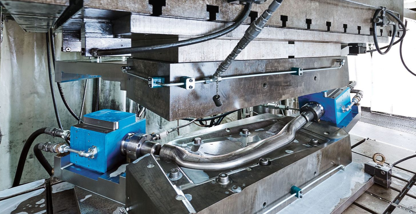
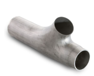
Anyway…given original engineers used hydroforming and so had some freedom on the form of the pipes, I reckon its ok to use splines (rather than arcs and straights) to form manifold pipe paths. My model will be restricted to circular sections pipes though which (in theory) was not a restriction on the original design.
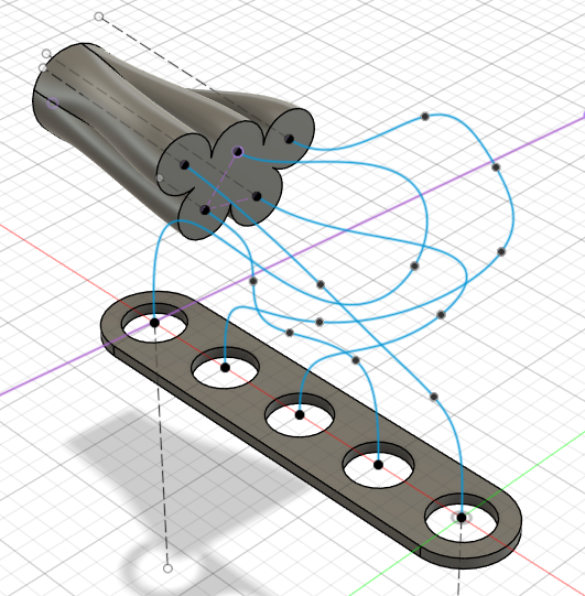
In Fusion I started arranging the 5 pipe (spline) layouts by eye trying to mimic the actual LFA design from photos above.
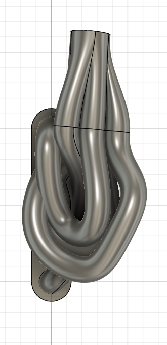
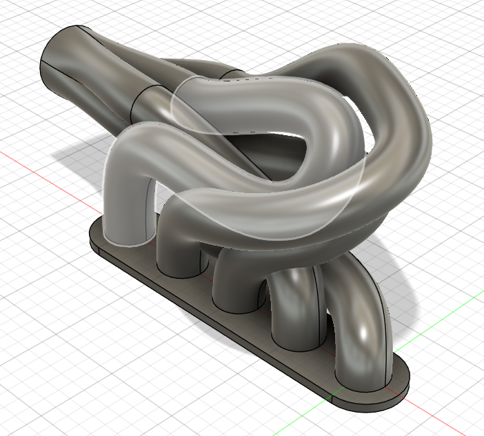
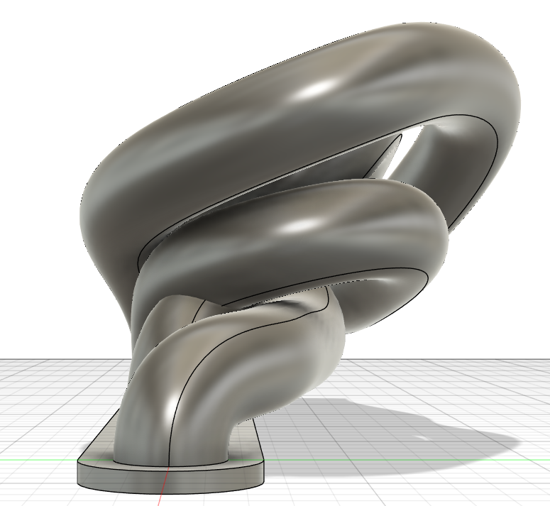
Here is a fusion model for my first take by-eye. Pipes are clashing and definitely not all the same length.
Anyway. I got bored so went 2026 computer power on it…next post