
In the video below Professor Malcolm Smith of Cambridge University (‘Prof Smith‘) tells a story of the design of his inerter and its controversy in F1 car racing. I thought it was interesting and decided to design one as a useless project to upskill in Fusion 360 and give my new 3D printer a workout. Beware that if you print out components and build one (files included below) it is likely serve no useful purpose!
But you never know!!
What is a ‘J-Damper’?
It is not a damper (nor a spring). As story goes (in video) McLaren called it a J-damper to mislead other F1 teams. Table below what an inerter is, compared to a spring and damper.
| Component | Force relationship |
|---|---|
| Spring |  Force proportional to displacement |
| Damper (shock absorber) |  Force proportional to velocity |
| Inerter (“J-damper”) |  Force proportional to acceleration  is the inertance constant (in kg). is the inertance constant (in kg). |
General mechanical principle
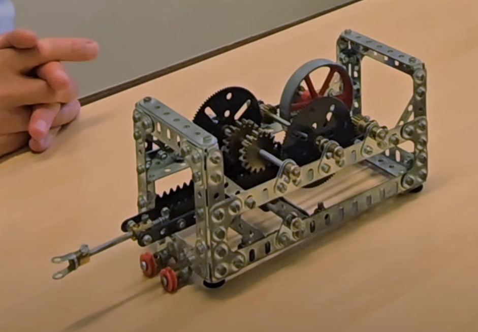
Snapshot of Prof Smith original 1997 Meccano model illustrates principle. Pushing/pulling the rod to the left sets the red flywheel spinning, through rack-and-pinion gearing. The system creates the ‘effect of mass’ without adding physical mass through the angular momentum of the flywheel.

The prof shows an early F1/compact prototype ‘j-damper’ (below). I have not really dissected this design but it rotates the flywheel though a gearing system off the centre rod which acts as a rack similar to the original Meccano prototype. This design (in hindsight!) is WAY better than mine – why I do not work at McLaren I suppose.

My inerter design
My design uses a helical screw to convert the linear motions of the rod to rotation of the flywheel, rather than a rack and pinion type mechanism. Two helices, one clockwise and the other counter clockwise, drive a planetary gear box which spins up the flywheel. The inerter push rod serves aa central axle. Friction is (kind of) addressed a some of off the shelf bearings and some PTFE/silicone lube on printed gears.
Design files
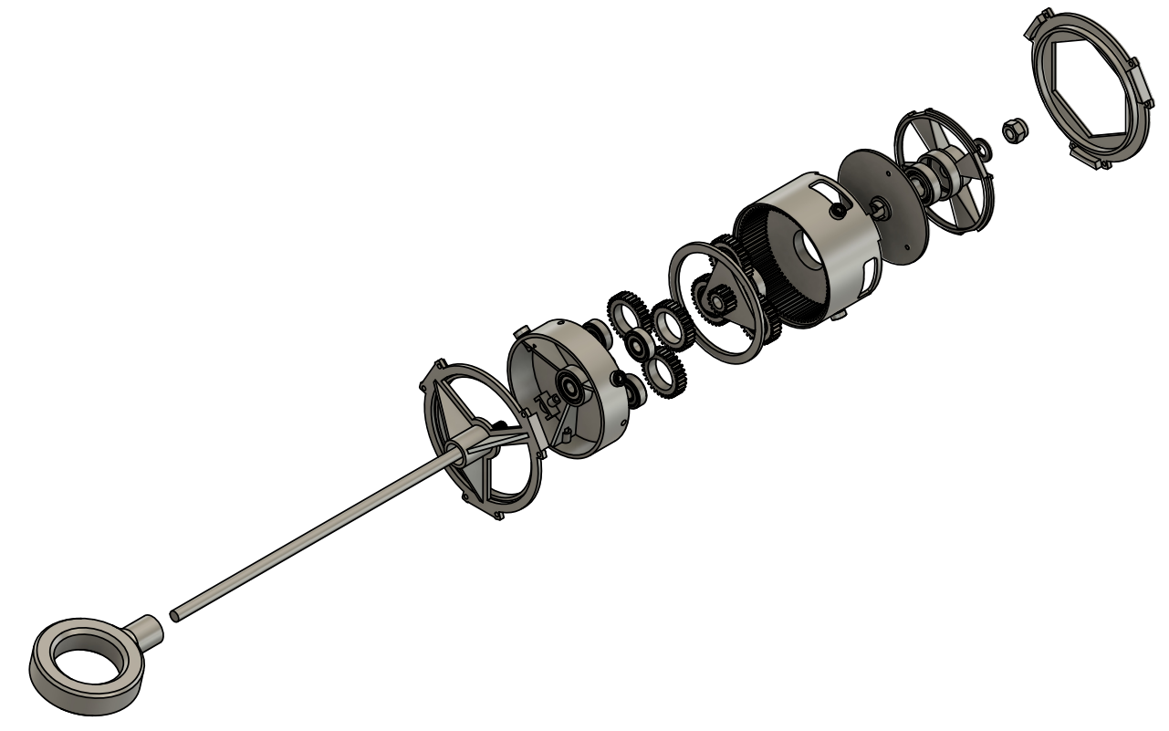
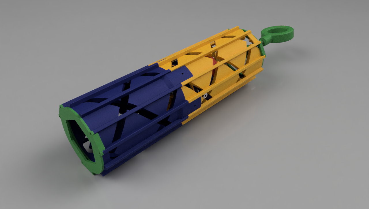
I printed mine on a Creality K1 Max using hyper-PLA filament. The expanded assembly render below does not show the outer helical housing which is two-part and these are by far the largest components. There are some screws missing here and there in assembly too.
Non printed parts:
- Bearings:
- 10# 104 ZZ 4x10x4 for helical plunger guides
- 8# 608 ZZ (skateboard wheel) bearings for planetary gears and main rod
- 2# 6001 ZZ 12x28x8 for mass flywheel
- 1# LMU8UU 8x15x24 linear bearing for where push rod goes into main outer housing end
- Screws:
- 7# M4x16mm hex sockets ultra thin wafer head bolt screws to fix 104ZZ bearings to walls of helical plungers
- 3# M4x 9mm (ish) grub screws for bearings between opposing helical plungers
- 6# M4x9 screw & nut pairs to fasten two halves of outer housing together
- 12# dia2.6mm 8mm long thread form screws for plastic to fasten end caps to main housing
- 400mm Smooth, hardened 8mm steel rod
- a couple of M8 flat washers
- M8 nyloc nut
The only workshop tasks were:
- cutting the groove for the circlip. I have a lathe, so easy.
- threading the hardened steel rod. This is easy with a high quality m8 cutting die and some oil but no-go with a cheap die (the ones you get in a set from the DIY store). Not sure if it helped me or not but I also heated the rod end with a flame torch to white hot and let is cool slowly (anneal) to take out some hardness.
- forming the OD 78mm ID 34mm flywheel masses from something heavy (I used lead sheet)
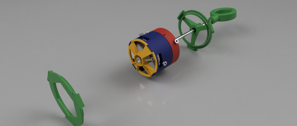
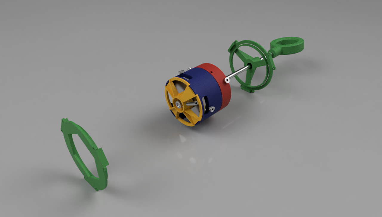
Below are renders from Fusion360. Kind of cool in United Colors of Benetton way.
Theoretical performance
Helices
Triple helices run along the design’s outer tube both clockwise and anticlockwise. The helices make a single revolution in 288mm, so the effective pitch of the counter rotations is $latex p_{\mathrm{helix}} = 144mm/rev $
Planetary gear train
The GF GEAR GENERATOR Autodesk Fusion 360 add-in is used to form the gears in the planetary gearbox. To come together correctly the sun gear , planetary gears and outer (internal) gear shroud needs to meet certain conditions in terms of number of teeth etc.
| Attribute | Value/ equation |
|---|---|
| Gear pitch |  |
| Gear contact angle |  |
| Number of teeth centre sun gear |  |
| Number of teeth planetary gears |  |
| Number of planetary gears |  |
| Number of teeth outer internal gear |  |
| For even placement of planetary gears on carrier, the condition to right must produce an integer |  |
| Transmission ratio |  |
| Radius from centre (sun gear and outer gear) to planet gear centres |  |
Initially i had a set of 3 gears sets in gear train which gave me a transmission ratio of  , ie one rotation of input shaft sun gear rotates flywheel 216 times. This was too much – you just could not overcome system friction and inertia to get flywheel spinning. I removed a set so gear train has a transmission ratio of 36.
So, the lead of my inerter,  – if the rod is moved 4mm the flywheel spins once.
Flywheel
My flywheel has an 80(.5)mm outer diameter. It consists of a 3D printed platter which is driven by the planetary gear box. There is 8mm clearance on either side of the platter in the gearbox housing to add mass (a metal flat ring either side). These are fixed with machine screws to the platter. I used lead sheet (2mm roofing lead) to make three stacked lead rings to give my inerter its rotational mass.
| Attribute | Value/ equation |
|---|---|
| Flywheel thickness |  |
| Flywheel inner and outer radii |  |
| Density of lead |  |
| Flywheel mass |  |
| Flywheel mass moment of inertia |  |
Inertance constant, b
This is really what is the inerter is all about.
| Attribute | Value/ equation |
|---|---|
| Inerter lead (the distance, not material!) |  |
| Flywheel inner and outer radii | |
| Density of lead |  |
| Flywheel mass | |
| Flywheel mass moment of inertia |  |
So what IS it and what does it do???
My design here weighs very little (~ 1 kg physical mass) but (in theory) behaves dynamically like a half-tonne mass, a x500 fold increase.
I have not got my head around how inerters (or the McLaren J-damper) might be useful in the world of high-performance automotive racing (aka Formula 1) but I think I can see a use for them in structural engineering where one might want to get the benefits of adding dynamic ‘virtual’ mass without adding physical mass that needs to be supported in the structures gravity load support system.
Mass damper in a skyscraper?
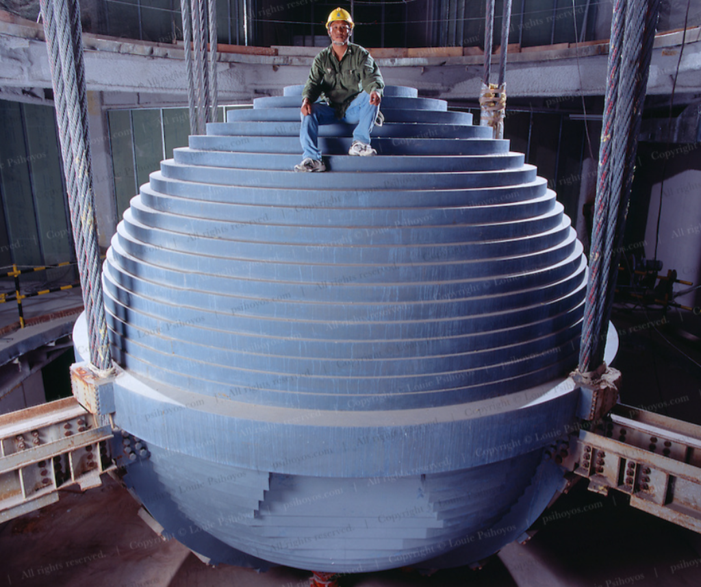
The photo below is the 660-tonne mass damper in the Taipai 101 tower (according to reddit). If the sphere is solid steel and 6m across, 660 tonnes sound about right by my numbers. This tuned mass damper changes and damps this 500m-high (101 floors) tower’s response to horizontal wind and earthquake loads. More on Taipei 101 here.
But the building’s engineer’s had to deal with the 440 tonnes of weight (in the technical gravity sense). With an inerter, one could reduce the physical mass but maintain the 660 tonne dynamic mass….
The reality: Apparently the Taipei 101 tower weighs 700,000 tonnes, so ~7000 tonnes a floor. A 660-tonne steel ball does not touch the sides gravity-wise! The mass damper ‘works’ by responding out of phase with the building mass, not by simply adding mass. A dumb steel sphere is likely cheaper and easier than a tricky inerter which needs maintaining and might fail mechanically when you need it not to!!!!
The wobbly Millennium Bridge
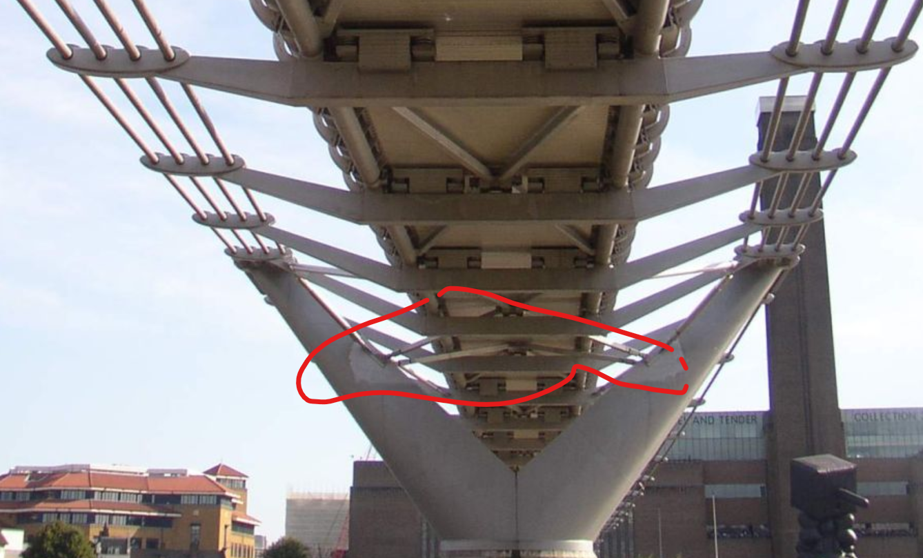
The Millennium Bridge in London bridges the Thames connecting St Paul’s cathedral and the Tate Modern. When is opened an issue arose with dynamic excitation due to people walking across the bridge falling into step with the bridges natural frequency. At the time it was quite a thing – the newspapers had blood for Millenium fails. Moreso though Chris Wise, who was one of my university profs at the time, was the bridge’s lead engineer.
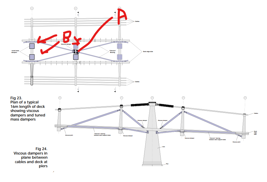
The solution was to add a viscous damper system to cross bracing under the bridge deck – A in the first photo below – and viscous dampers at support arms (second photo). The diagram below is from the paper Dallard et Al’s paper The London Millennium Footbridge which explains is great detail the cause of the issue and the remedy. As paper explains, the retrofit also included vertical tuned mass dampers (B) since engineers were worried having fixed the lateral wobble, people walking might start bobbing up and down in unison instead (I am paraphrasing!).

I wonder if a tuned inerter (damper) design could have been an option to address the bridge’s shakes?
Short answer: Chronologically, probably not. According to this document, Professor Smith reckons he conceived the idea in the late 90s but the patent was filed in 2001 and research published in 2002. Out by a whisker.
Technically though, I reckon it might have been a potential solution, had it existed. The crux of the issue with the bridge was that is was design to be ultra lightweight and the not-dissimilar mass of ‘marching crowds’ played havoc. An inerter-based system might have been a means of increasing the dynamic mass of the bridge 10-20 fold while adding little gravity loading on the slender design.
Anyway – they fixed it. The bridge is great and it tells a story.
Wrapup

For the moment my 3d-printed inerter will remain a curiosity:
- The inertance (a x500 increase in mass) is a little high. Taking out two of the three lead discs helped.
- The double helix design was probably the wrong route to take from the onset – its not that smooth since one plunger tried to fall into countertrack of the other depending on direction. I think this could be designed out if the helices did not occupy the same radial space but that would be a quite different design.