
This older post describes my first go at rejuvenating an old Kenwood hi-fi amp – the focus was on automatically switching the thing off & on depending on whether there is no audio signal. I was doing this by using an Arduino Uno to detect the voltage signals on RCA audio input. It was a little glitchy, for instance, it sometimes itself into frazzle clicking on and off in a feedback loop since powering down caused a CLICK sound from the amp.
Here I am revisiting the project – I have a better way of doing it using an ESP32 microcontroller. (FYI I bought 10 ESP32s a while ago off Aliexpress). Hopefully, this post will inspire bringing some old analogish hi-fi amps out of some attics. Perfect lockdown project (I live in New Zealand – we are behind on these things!)
The magical little ESP32 means you build and program a home-cooked BlueTooth Audio dongle plus use all the other programmable microcontroller(MCU) magic. Now, I know I could stick a whole internet radio on an ESP32 but wanted to keep the old amp relativity ‘pure’ and adding rather ubiquitous BlueTooth streaming of ‘any’ audio source did not seem that disruptive.
Service Manual
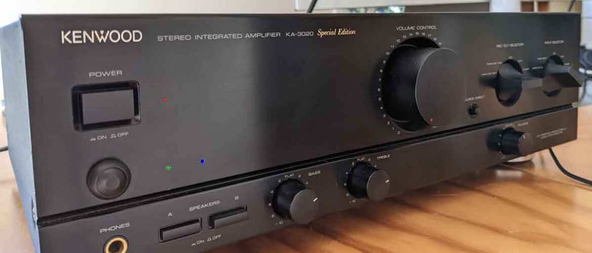
I came across the service manual for the Kenwood 3020SE online (which incidentally was What HiFi’s Amp of the Year 1994). Link to manual here, just as a reference: my mods are largely non-destructive to original electronics. Love the exploded view in the manual.

⚠️Warnings ⚠️
Oh, and please heed the warnings on the back of the amp regarding high voltages and large capacitors carrying change.
Hardware mods

- An ESP32-WROOM-32U + external antenna. I reckon the amp’s metal case might be quite effective Faraday cage? …so external antenna mounted to back of amp. Already looks modern with this! My ESP32 board model has a USB jack that can power the unit so I use a regular old main-5V adapter. I will leave it to your imagination on how to hide this in the amp box and connect to an available mains supply…🔌⚡.
- An Adafruit I2S stereo decoder (ADA1334A). I just used this units 3.5mm output jack and connected to TAPE/DAT 2 input phono RCA plugs. You could use the ESP32’s internal DAC to produce audio signal but you would be taking a hit in turns of quality and bother. Audio data is transferred from the ESP32 to ADA1334A
- A 240V 10A mains-rated relay – see below on power control. My ESP32 dev board has a 5V pin, so I use this to power relay, and ESP32 3.3V for the control signal
- 3 colored LEDs + 330Ω resistors: Blue for BT connection state, green for ‘mode’, and a red power one which replaces the amp’s one.
- A push button for ‘mode’ control: single press brings out of standby, long press forgets the currently connected BT device. Long press at powerup puts it in OTA firmware update mode (see below)
- A levered microswitch to mechanically detect input selected on amp’s input selecter control knob.

Wiring is ‘standard’ for all the above sub circuits – nothing complicated. Follow the links. Incidentally, for the buttons the avdweb_Switch library (see below) do not require you to include pullup(down) resistors.
The green and blue LEDs and the button are mounted into holes drilled clear Perspex glued to the back in the aluminium fascia of the amp. They align with some holes I drilled in the fascia matching similar existing holes. The red LED replaces the amp’s red power LED – I glued it with a spot of hot glue.
Solder and circuit fabrication
I think I have turned a bit of a corner here technique-wise. Might share in another post. I used to dread this bit but I think I have clocked it; no flaky connections is a first for me. Lego bits are my mounting solution.

Power control to amp
In my previous build, I had the MCU-controlled relay in series with the amp’s actual power button. This is kind of confusing as a user experience. In this build, I have replaced the function of the original power button entirely with the MCU-controlled relay and re-wired the original power button into the MCU, so the power control to the main amp is now entirely fly-by-wire via the ESP32.
The power LED is now MCU-controlled too.
Detecting selected input is TAPE/DAT 2
Auto standby is only ‘active’ when the input knob on the amp is set to TAPE/DAT 2 (now BlueTooth). I tried to hardwire into a physical selector for signal, but it adversely affected the sound output ended up with a mechanical solution. Its a bit of PMMA and a lever microswitch pulled out of a security motion sensor (part of the tamper detection).

Code
Here on Github with some more notes: it is set up as a PlatformIO project using Arduino Core framework. It uses a couple of libraries:
- ESP32-A2DP lib takes care of the Bluetooth connectin and audio output (using I2S…not the same as I2C) to the stereo decoder.
- The avdweb_Switch library takes care of debouncing buttons and distinguishing beteen single click, double click and long press.
- A third library, ESP32-blinker, is my own and is currently set up as a git submodule on repo. I could not find a decent LED blinking lib for ESP32 which uses the
Tickerso wrote my own.
Also includes OTA wifi updating of firmware (on local network). I ended up having to write a bespoke partition table to get OTA working and it all fitting on the ESP32 model I have (4MiB? Which I think is pretty standard). This is all included in the repository. You put the amp into OTA mode by holding the mode button when you power up. All 3 LEDs blink.