
I thought I might make a CNC machine (about 3 years ago), but got side-tracked. I have recently had a renewed interest:
- I decided I would try and build it just from crap I had lying around in the garage. See if I could just hack together a CNC machine out of my hoarded junk.
- I am going to just wing it, no plans or design, and see where I end up.
I’ll try and keep adding posts as I progress.
Some ‘Where-things-are-at’ Photos
The photos below are a snap-shot of where things are at as of today. I have done quite a bit in the last fortnight so we are hitting the ground running.

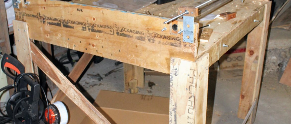
This is at, as it currently stands. Yes. I know it looks shit, but that is the beauty of it. right? The main bed is a palette. I know, I know, (To Pinterest) palettes are palettes, there are not for building stuff with, they are for carrying stuff to build stuff with. You do NOT make your bed out of a palette. BUT, I got swept up in palette-mania, and so had a palette I then had to dispose of (they are big: 1.2m x 1.2m in this case) and I felt making it into a CNC machine was easier that (1) breaking it up, or (2) driving to a forest and replanting. I wouldn’t do that REALLY BTW, mainly becouse ‘1.2m things’ do not fit in my new car, but they did in the old one. grrrre. more on that another time.

Mount on YY-bridge for the y-axis stepper motor. steel SHS courtesy of skip behind the University of Auckland engineering school.

Stepper mount to Y-direction (i.e. moves the YZ-bridge). There are two of these (and so two motors). I am debating whether the two motors should be coupled together (the downside is that this would add friction) or if I can ‘trust’ them to not miss steps. Steel SHS as previous photo, except in the interim this has been an (unsuccessful) spreader on a homemade BBQ

NEMA 17 stepper motor ‘mount’ (the ply) and my home grown coupler.

My home made coupler from 5mm NEMA shaft to M8 drive screw. 8mm to 5mm reduces courtesy of bits from a few of those kids scooters I found in s skip about 5 years ago. Blue stuff is locking fluid (which might be my new second best smell after WD-40).

The y-direction mount. The Z-direction and tool will go on here on those 4 m8 stubs somehow. The mount is essentially a linear bearing made of skateboard bearings, similar to the X-direction ones which support the bridge. The wood block in the centre houses the connection to the drive rod. I increased degrees of freedom (can rotate in two directions) to reduce the load on the single motor which drives this axis.

The ‘thing’ that transfers load from the drive rod(s) to the bridge. consist of two M8 couplers (the bronzey bits) with a washer in between. Ignore the grey aberrations on the couplers – these are from a previous failed idea for this connections. The washer keys into the slots in the timber blocks. The couplers can slide in one direction in the blocks (and also rotate in that plane too). These two degrees of freedom loosens everything up so there not too much torque on motors while having no detrimental effect on the X-axis accuracy.

One of the two X-direction home-made ‘linear bearings’. See aobve for Y-direction equivlanet.

X-direction. The tube is ~30mm dia. A curtain rail.

Y-direction again. The ‘slice’ of aluminium in the centre of the photh, that holds the timber block, was rescued from a work aluminium-framed window extrusion sample.

What possessed my camera to focus where it did – mid-way along one of the X-direction (curtain) rails? I suppose a bad workman blames his equipment, so I should belt up! Whiteness on the left is (one of) the m8 drive rod(s)